Welcome to automatic models creation of Cable-stayed Bridges.
ICDAS Cable-stayed Bridges allows you to create Cable-stayed Bridges in Revit 2016 and Lusas 15.1-0 for geometry
and analysis model, respectively.
Automatic model creation of cable stayed bridge will help you to plan, design, build and manage the project easier
and much faster. ICDAS has many years of experience in this field acquired through researches and selected bridge
projects worked on in the previous consulting engineering companies in Denmark.
The following examples of cable stayed bridges are created automatically by ICDAS Add-Ins in Revit. Together with
Revit model you obtain also a Lusas.cmd file when running Add-Ins in Revit. By importing Lusas.cmd file in Lusas
you will also get a 3D FEM model automatically.
Danube River Bridge design proposal
The bridge is crossing the Danube River connecting Braila and Smardan in Romania. The bridge site is as shown below.
Figure: Corridors for the bridge overpass and the Danube river underpass, AutoCAD Civil 3D.
Figure: Longitudinal profile slope of 0.60%
Proposal for the corridors are designed in Civil 3D as a need of input for Revit Bridge. The final corridors can be easily
updated in Revit for all drawing details. The Civil 3D working steps and link to Revit are outlined in details in registered
licence CSB 2016.00R. It includes also guidelines for automatic creations of the deck, pylon, pier and abutment in ICDAS
families. Some of the basis rules of geometry for these elements are outlined in Geometry model and Analysis model.
The width of the Danube river at the bridge location is about 600m which perfectly fits to the cable stayed bridge,
having the spans 150+302+150m.
Automatic models creation allows us to test appearances of the cable stayed bridges for varying shapes of the pylons.
By changing eccentricities input for the pylon legs on top and at the bottom, one will get three different looks for the
same bridge as shown below (dimension are given in mm).
Figure: A-Pylon (EccTop, EccBot) =(4000, 16100). Harp cables system h5=6300.
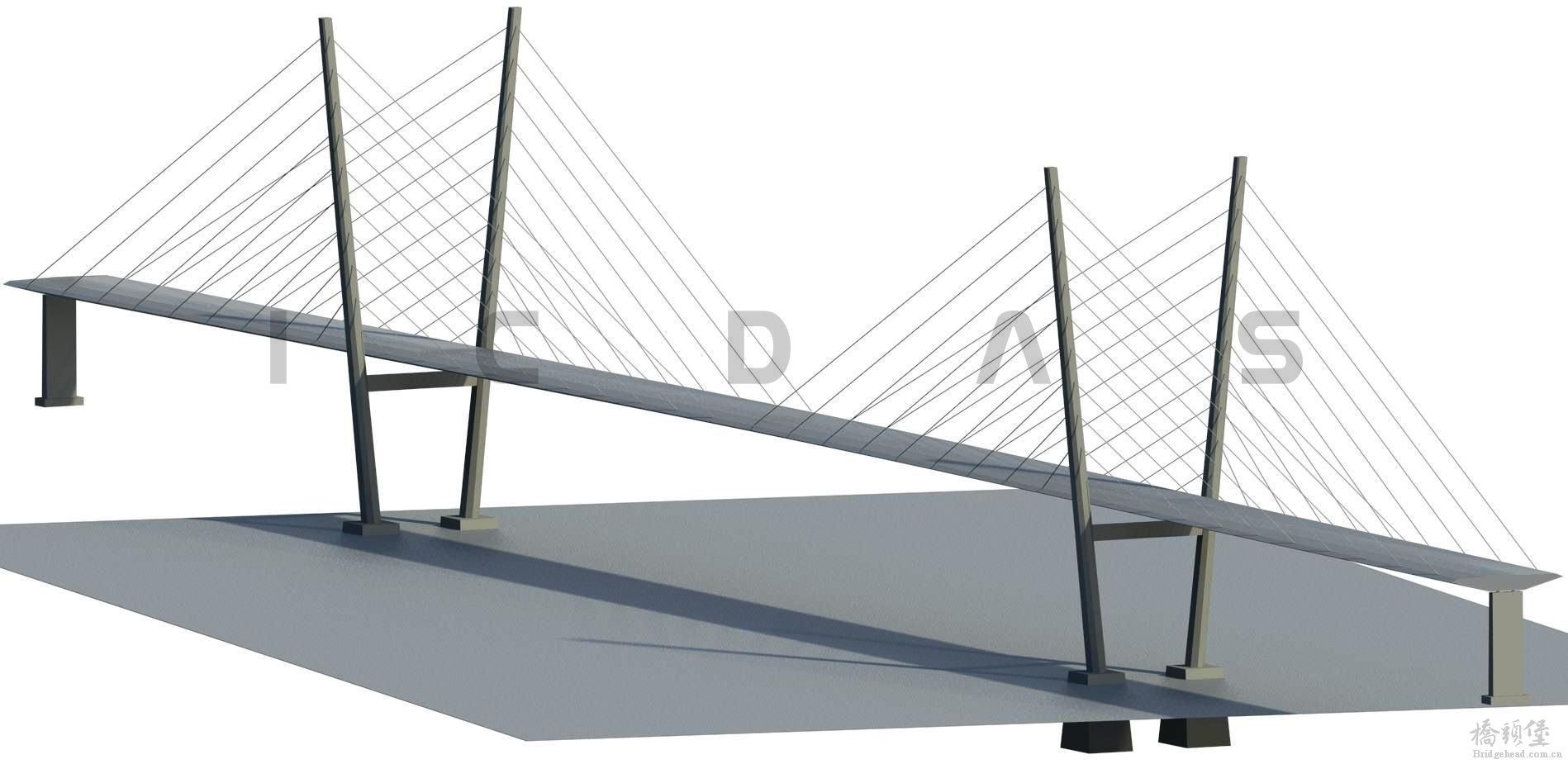
Figure: V-Pylon (EccTop, EccBot) =(20600, 10600). Harp cables system h5=6300.
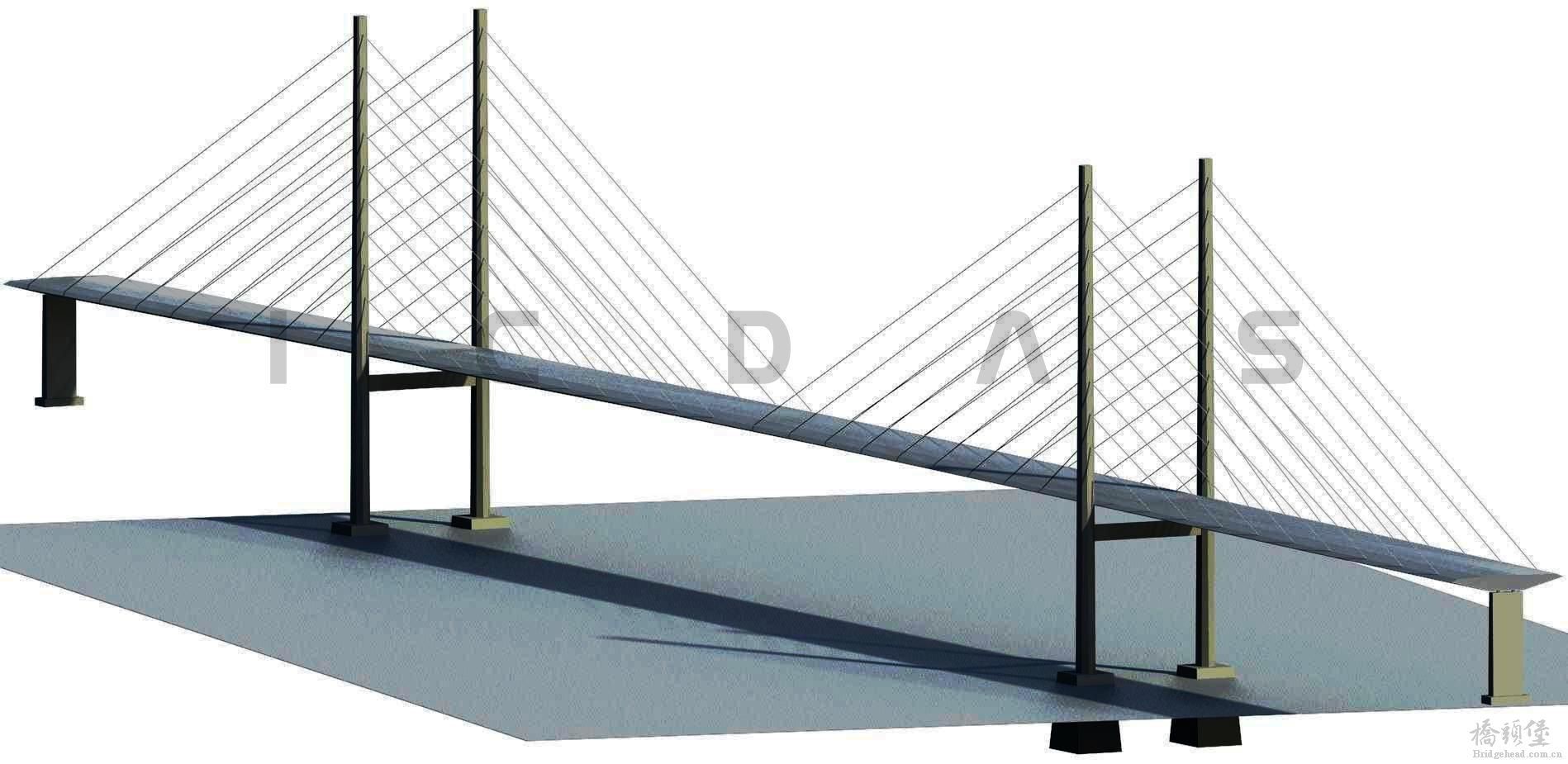
Figure: H-Pylon (EccTop, EccBot) =(13000, 13000). Harp cables system h5=6300.
The next three bridges show the same shapes of the pylons as the above three, but the cables are arranged in
a semi-fan system with vertical spacing h5=3000mm at the pylons.
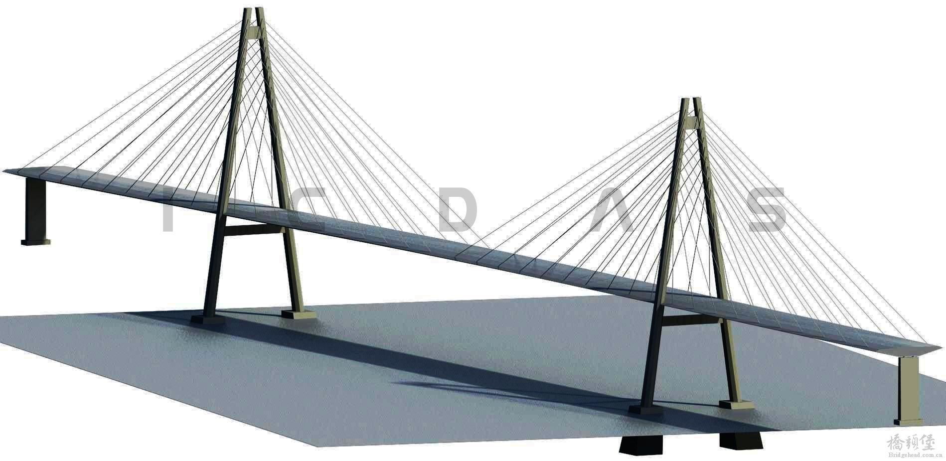
Figure: A-Pylon (EccTop, EccBot) =(4000, 16100). Semi-Fan cables system h5=3000.
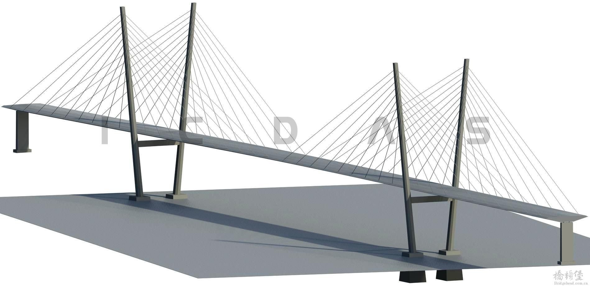
Figure: V-Pylon (EccTop, EccBot) =(20600, 10600). Semi-Fan cables system h5=3000.
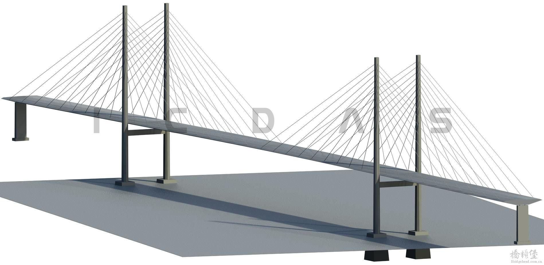
Figure: H-Pylon (EccTop, EccBot) =(13000, 13000). Semi-Fan cables system h5=3000.
Also cross sections of the pylons, piers, foundations and cables can be changed fast as well. They are created in family
ICDAS_3DPier.rfa and loaded into the bridge model. Changing cross sections of the streamlined deck box and the
lengths of the spans takes only few minutes to be updated to the bridge corridor overpass created from AutoCAD
Civil 3D.
ICDAS Cable Stayed Bridges also creates automatically an associated 3D FEM model in LUSAS Bridge.
Thus, using ICDAS Automatic Models Creation will save time for both of geometry and analysis models.
Updated 03-06-2015